CN


Fiber-coupled laser sources change the architecture of compact optical instruments. Instead of steering a free-space beam through a maze of mirrors, mounts, and periscopes inside a crowded chassis, the laser is delivered through an optical fiber patchcord to the port where the instrument actually needs light. That shift is not cosmetic. It affects alignment time, mechanical stability, thermal layout, serviceability, and how small an OEM can make a confocal head, Raman probe, industrial sensor, or inspection module.
This article focuses on laser beam delivery in compact instruments and industrial equipment: flexible integration, simplified optical layouts, and reliable transmission. It is not a fluorescence-excitation efficiency study and not a general buyer’s-guide rewrite. The product reference is Sunlonge’s SLC300 / SCL3000 fiber-coupled laser platform.
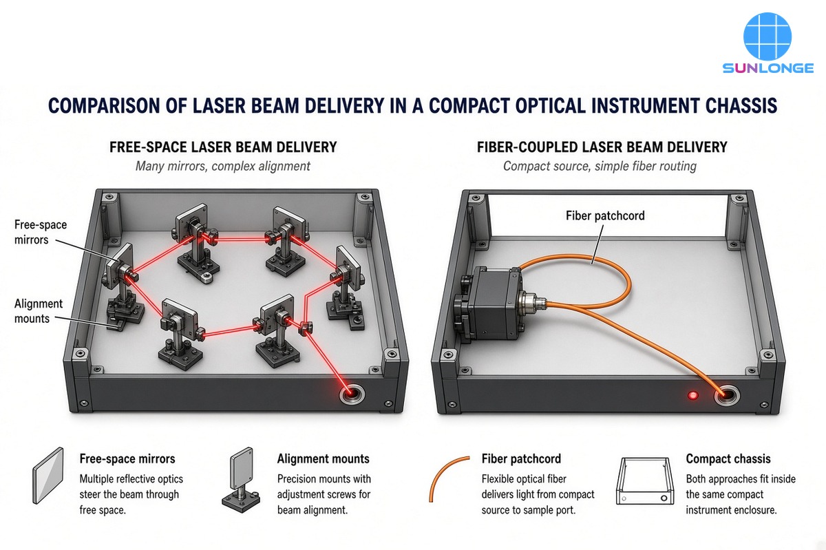
What “Beam Delivery” Means Inside a Compact Chassis
Photonics references such as RP Photonics describe laser beam delivery as transporting and conditioning light from the source to the application so that focus size, direction, polarization, beam quality, and power arrive as required. Two primary architectures dominate:
- Free-space delivery — mirrors, lenses, beam expanders, and kinematic mounts in air (or vacuum).
- Fiber delivery — guided propagation in single-mode, multimode, polarization-maintaining, large-mode-area, or hollow-core fiber, often with free-space launch/collimation only at the ends.
Hybrid systems are common: a fiber-coupled laser source already finishes the hard coupling step at the factory, then the instrument designer only collimates or focuses at the output.
In a large optical table, free-space paths are manageable. In a compact optical system—a 1U module, a handheld probe, a sealed industrial head, or a confocal scan box—every mirror mount consumes volume, access panels, and alignment budget. Fiber-coupled laser sources move most of that complexity out of the instrument volume.
Why Free-Space Paths Struggle in Compact Instruments
Free-space routing inside a small enclosure creates recurring engineering costs:
| Challenge | What happens in a compact free-space path | Why fiber delivery helps |
| Mirror count & fold geometry | Multiple 45° folds needed to clear electronics and heat sinks | Patchcord routes around obstacles without preserving a clear optical line of sight |
| Alignment degrees of freedom | Tip/tilt at each mount; drift stacks | Factory-coupled SM/PM output; instrument aligns mainly at the collimator |
| Pointing stability | Mount creep, chassis flex, and thermal gradients steer the beam | Guided mode largely insensitive to chassis flex along the fiber run |
| Service & modularity | Moving one board can break the beam path | Swap or reposition the laser module; reconnect the fiber |
| Safety & stray light | Open beams need shrouds and dumps | Light stays confined until the intentional output |
RP Photonics notes that fiber delivery’s primary advantage is high routing flexibility, especially toward moving heads, while free-space articulated arms remain bulky. The same logic scales down to instrument interiors: flexibility matters when the “distance” is only 200–400 mm but the path must snake past PCBs and fans.
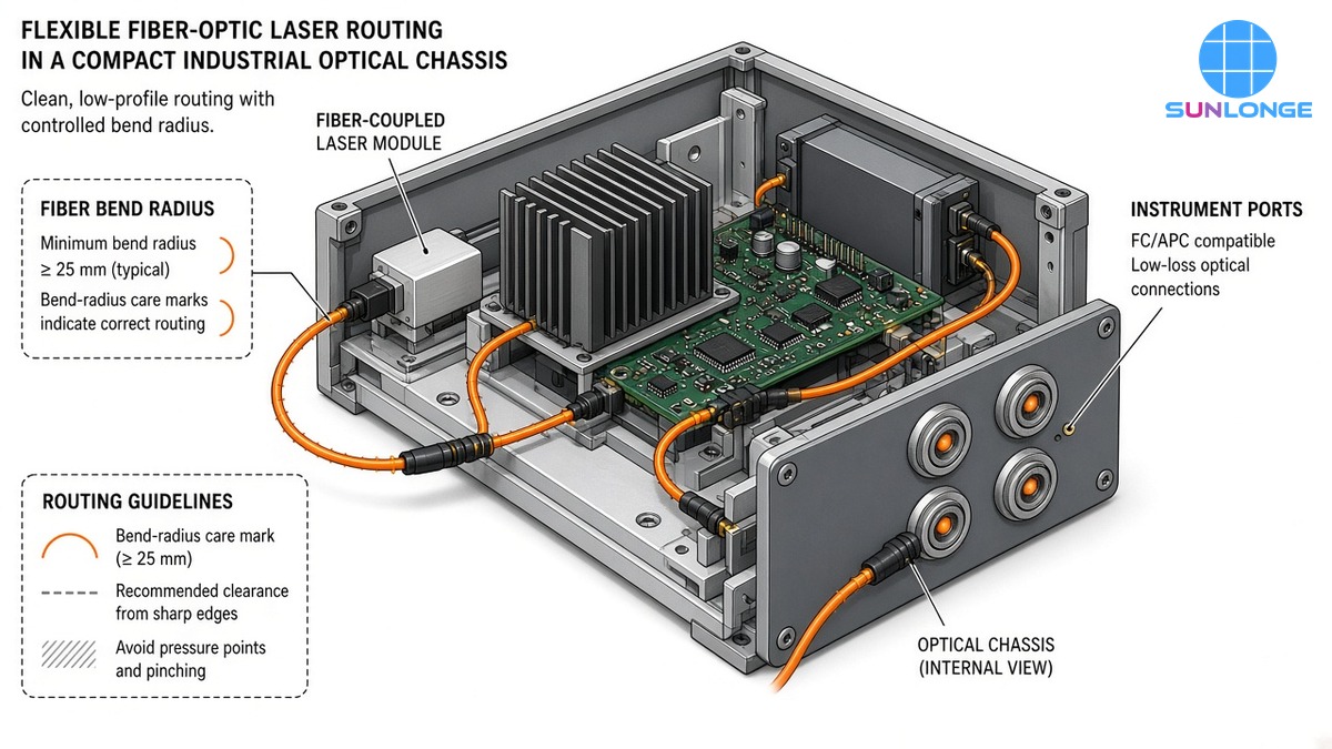
How Fiber-Optic Delivery Simplifies Optical Layouts
1. Decouple laser location from the optical axis
With a fiber-coupled laser source, the laser body can sit where thermal design wants it—against a heat sink, on a vibration-quiet shelf, or outside a sterile/process zone—while the fiber brings light to the sample port. OEMs no longer need the laser’s optical axis to coincide with the instrument’s measurement axis.
2. Collapse the “alignment tree”
A free-space chain of N mirrors has N tip/tilt adjustments and N opportunities for clipping. Fiber delivery collapses that to:
- a stable coupled output at the source connector, and
- a collimator / focusing optic at the instrument port.
That is especially valuable for field service: technicians replace a fiber or clean a connector instead of rebuilding a periscope.
3. Preserve a predictable spatial mode for focusing
Single-mode (SM) and polarization-maintaining (PM) fiber outputs are well suited to confocal excitation, interferometric probes, and other compact systems that need a clean, focusable mode. Multimode fiber can deliver more power but may degrade beam quality and increase speckle; choose based on the application, not only on watts.
4. Enable sealed and modular industrial equipment
Industrial sensors often need IP-rated housings, quick swap of laser modules, and cable glands. A fiber patchcord is a natural interface between a sealed optical head and a replaceable laser electronics box.
Reliability Numbers That Matter for Compact Delivery
Honest system design uses public coupling and reflection figures—not invented “uptime” percentages.
Alignment sensitivity of single-mode coupling
Launching a diode into single-mode fiber is intrinsically tight. SPIE literature on laser–fiber coupling notes that monomode coupling typically requires lateral/vertical errors below about 0.5 µm and angular errors below about 2° to keep coupling loss under roughly 2 dB when the laser and fiber are aligned as separate elements. That is why instruments prefer a factory fiber-coupled laser source: the micrometer-class alignment is done once in production, not again on every OEM assembly line.
Fresnel reflections at fiber facets
At a normal-incidence air–glass interface (n ≈ 1.5), Fresnel power reflectance is about 4% per facet (~0.18 dB). Open University teaching material and FOA references use this classic figure; two uncoated air–glass interfaces in a connector gap can cost on the order of 0.3–0.35 dB before mode-mismatch losses. Anti-reflection coatings, physical-contact connectors, or angle cleaves reduce return loss that can destabilize sensitive lasers.
Mode matching and theoretical coupling
Laser Focus World and vendor application notes emphasize that an ideal Gaussian matched to the fiber mode can approach very high theoretical coupling (literature often cites >99% before reflections), while real diode beams are elliptical and astigmatic—so packaged fiber-coupled sources earn their keep by including the beam-shaping and alignment that a compact chassis has no room to host.
What this means for OEMs
| Topic | Practical figure (public sources) | Design implication |
| SM lateral alignment for low loss | ~< 0.5 µm class (SPIE coupling discussion) | Prefer pre-coupled modules over in-chassis diode-to-fiber launch |
| Angular tolerance (SM) | ~< 2° for <2 dB class loss (same class of analyses) | Protect connectors; avoid strain that tilts ferrules |
| Fresnel reflection per air–glass facet | ~4% | Specify PC/APC connectors or AR-coated ends when return loss matters |
| Ideal SM mode overlap (theoretical) | Can exceed ~99% before reflections | Real efficiency limited by diode beam shape + reflections + connectors |
| Architecture choice | Fiber = flexibility; free-space = max power / exotic wavelengths (RP Photonics) | Compact visible/NIR instruments usually favor fiber-coupled sources |
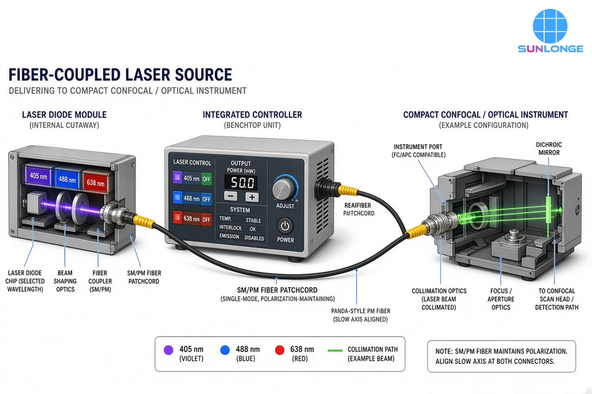
Sunlonge SLC300 / SCL3000: Compact Fiber-Coupled Laser Sources
Sunlonge’s SLC300 (also referenced as SCL3000 on product copy) fiber-coupled laser light sources are built to deliver high-intensity output through an optical fiber patchcord for optical microscopies such as confocal and super-resolution systems—and, by the same architecture, for other compact instruments that need guided beam delivery.
Published product details:
| Parameter | Sunlonge SLC300 / SCL3000 (published) |
| Wavelength options | 405 / 488 / 520 / 638 / 660 / 785 / 850 / 980 nm(customer wavelength design supported) |
| Fiber output | Single-mode polarization-maintaining (SM PM)fiber-coupled output |
| Power | about 20–30 mW per wavelength |
| Channeling | Single-channel only (cannot combine wavelengths in one SLC300 unit) |
| Control | Manual knob 10–100% plus remote control |
| Size | 186 × 160 × 63 mm |
| Integration | Control and heat dissipation integrated into the laser system |
| Stated applications | Confocal microscope; super-resolution microscope |
Those numbers map directly to compact-system needs:
- 186×160×63 mm is a benchtop/instrument-bay footprint, not an optical-table laser head with a separate driver crate.
- SM PM output supports polarization-sensitive and mode-clean delivery into scan heads.
- 20–30 mW per line is a common excitation class for many confocal and inspection channels without forcing high-power multimode fiber compromises.
- Single-channel keeps the module simple and thermally stable; multi-line instruments use multiple modules or a separate combiner rather than overloading one chassis.
- 10–100% knob + remote lets software or operators set delivery power without rewriting the optical path.
Free-Space vs Fiber-Coupled Delivery: Compact-System Scorecard
| Criterion | Free-space mirrors in chassis | Fiber-coupled laser sources |
| Layout freedom | Needs clear optical corridors | Routes around electronics |
| Alignment labor | High; multi-mount | Low at instrument; factory-coupled source |
| Sensitivity to chassis flex | High | Low along fiber run |
| Polarization control | Waveplates + mounts | PM fiber option (as on SLC300) |
| Service | Realign after repairs | Connector clean/replace; module swap |
| Best fit | Ultra-high power, exotic λ, vacuum paths | Compact instruments, confocal/industrial modules |
| Sunlonge example | — | SLC300 / SCL3000 SM PM, 20–30 mW, 186×160×63 mm |
Illustrative engineering note (not a Sunlonge certification): moving from a three-mirror fold to a fiber patchcord can remove three tip/tilt stages and their thermal drift terms from the instrument error budget. The remaining tasks are connector care, bend-radius control, and output collimation—usually fewer variables than a free-space maze.
Integration Guidance for Compact Optical Systems
- Respect bend radius. Do not pinch fibers against sheet-metal edges; use clips that enforce a gentle radius.
- Manage connectors. Cap unused ports; clean before mate; prefer PC or APC finishes consistent with your return-loss needs.
- Strain-relieve the jacket. Mechanical load belongs on the cable boot, not the ferrule.
- Place the laser for heat, the fiber for light. Put the 186×160×63 mm body where airflow exists; run fiber to the optical port.
- Single-channel planning. For multi-wavelength confocal systems, plan multiple SLC300 units or an external combiner—do not assume one module emits several lines.
- Remote dimming in software. Use the 10–100% remote interface to keep optical alignment fixed while power tracks recipe steps.
- Verify delivered power at the port. Measure after the fiber and collimator; do not assume diode faceplate power equals sample-plane power after connectors and optics.
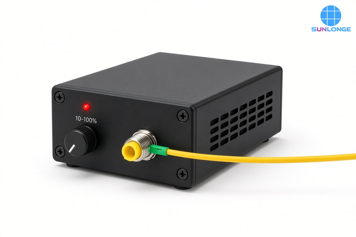
Where to Specify Fiber-Coupled Laser Sources
Choose fiber-coupled laser sources when the design priority is reliable beam delivery in a small volume: confocal and super-resolution illuminators, compact industrial inspection heads, OEM optical sensors, and sealed equipment that must be serviced without rebuilding mirror trains. Free-space still wins for some ultra-high-power or specialty-wavelength paths, but most compact visible/NIR instruments benefit from guided delivery.
Explore the Sunlonge fiber-coupled platform here: Fiber-Coupled Laser Sources (SLC300 / SCL3000) (SLC300 / SCL3000)](https://www.sunlonge.com/product/2344.html).
Key Takeaways
- In compact optical systems, beam delivery architecture often limits size and stability more than the laser diode itself.
- Fiber-coupled laser sources relocate micrometer-class coupling into a factory module and let OEMs route light with a patchcord.
- Public coupling literature shows why that matters: SM launches can require ~0.5 µm lateral precision, while each uncoated air–glass facet reflects about 4%.
- Sunlonge’s SLC300 / SCL3000 package—SM PM fiber, 20–30 mW, 10–100% control, 186×160×63 mm, single-channel wavelength options from 405–980 nm—is built for confocal-class and other compact instrument delivery, not for open-beam mirror mazes.
If your compact instrument still uses three mirrors to dodge a power supply, it may be time to treat the laser as a fiber-coupled utility, not a free-space guest.