CN


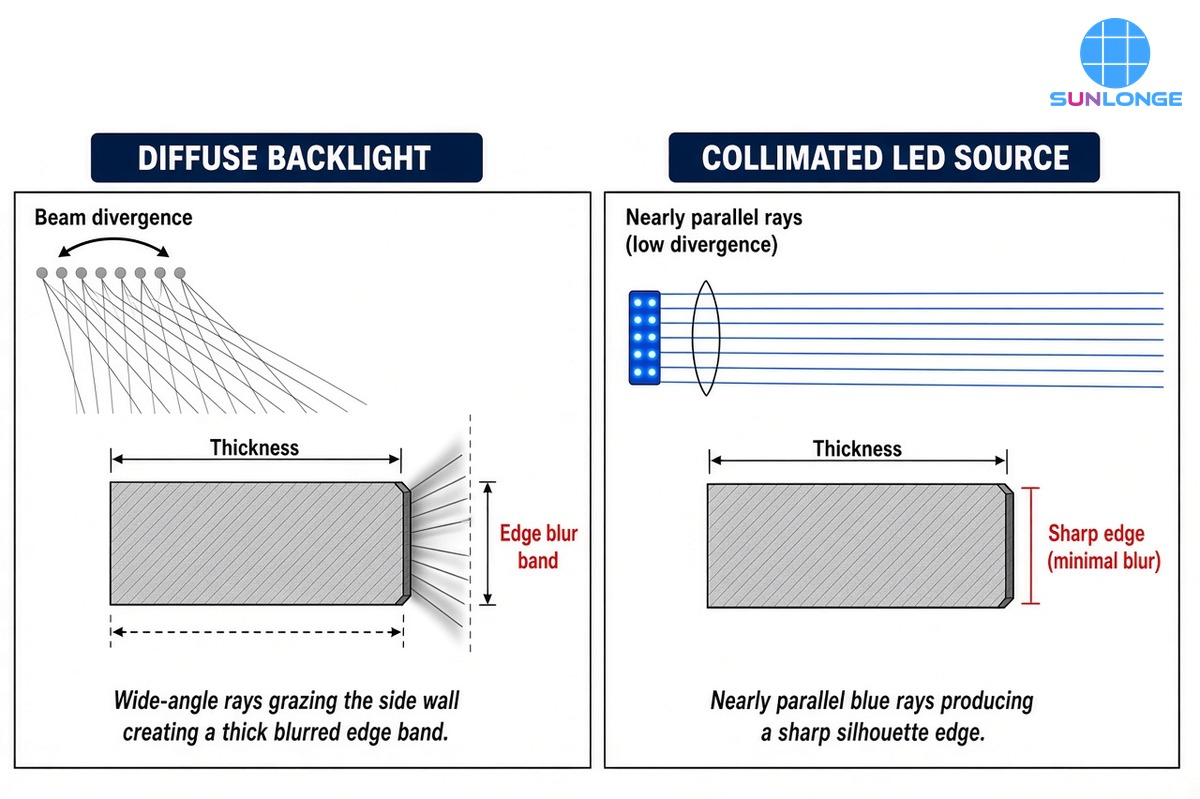
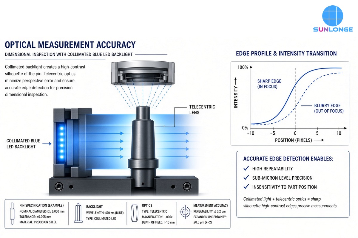
A collimated LED source does not make an optical gauge smarter by itself. What it changes is the geometry of the lightthat reaches the part. In optical measurement instruments, precision metrology stations, and dimensional inspection systems, most silhouette and edge-based readings assume a clean brightness step at the feature boundary. Diffuse or poorly collimated illumination breaks that assumption: rays arrive at many angles, graze thick side walls, and turn a knife-edge into a soft band of pixels. The software still reports a dimension—but the number drifts with part thickness, surface finish, and placement.
This article focuses on that measurement chain: how residual beam divergence creates geometric edge error, why consistent irradiance across the field matters for repeatability, and how a purpose-built collimated LED source such as Sunlonge’s SLC9300 and SLC6300 supports gauging setups where commodity diffuse lights fall short. It is not a general “what is collimation” primer, and it is not a machine-vision defect-detection essay; the goal is optical measurement accuracy.
Why Optical Measurement Is Sensitive to Illumination Geometry
Optical metrology is a large and growing field. Industry analysts at IMARC Group valued the global optical metrology market at about USD 3.4 billion in 2025, with a projected path toward roughly USD 5.1 billion by 2034 (about 4.5% CAGR). That spend covers measuring microscopes, video measuring machines, multi-sensor CMMs, profile projectors, and related systems—tools that depend on sharp, stable optical edges as much as they depend on cameras and software.
For silhouette gauging and many telecentric setups, the camera algorithm typically finds an edge by locating a steep intensity transition (for example a 50% threshold or the peak of a derivative). That works when:
- The geometric blur band at the edge is narrow compared with the tolerance and the pixel size.
- Irradiance on the background is even enough that the threshold does not wander across the field.
- Working distance and part height do not reintroduce angled rays that the optics cannot reject.
A collimated LED source is designed to help with all three by reducing the angular spread of the beam before it hits the part.
Beam Divergence, Part Thickness, and Edge Error
When light is not collimated, the edge of a thick part images as a band, not a line. A useful first-order bound is:
edge blur ≈ thickness × tan(θ)
where θ is the half-angle of rays that still enter the imaging cone.
An application note from Noctvision walks through a concrete gauging case: a 3 mm thick press-cut metal part imaged with an object-side telecentric lens of NA 0.025 (acceptance half-angle ≈ 1.43°). With a diffuse backlight that fills that cone, the geometric blur bound is about 3 mm × tan(1.43°) ≈ 75 µm—roughly 7.6 px at their ~9.86 µm/px scale. That blur is already wider than a 40 µm chip the gauge is meant to catch.
The same note estimates that placing a 1 mm emitter at the focus of a 100 mm collimator yields a residual divergence of about 5 mrad (0.29°). On the same 3 mm part the blur bound shrinks to roughly 15 µm (~1.5 px)—about a fifth of the diffuse case. Enlarge the emitter to 3 mm for more brightness and divergence triples, widening the band again.
| Condition (3 mm thick part, NA 0.025 example) | Approx. divergence / acceptance | Approx. edge blur bound | Practical meaning |
| Diffuse backlight filling lens NA | ~1.43° acceptance filled | ~75 µm (~7.6 px) | Edge softer than many defect/tolerance targets |
| Collimated LED, 1 mm emitter / 100 mm EFL | ~0.29° (5 mrad) | ~15 µm (~1.5 px) | Sub-pixel edge algorithms become meaningful |
| Collimated LED, 3 mm emitter / 100 mm EFL | ~0.86° | ~45 µm (~4.6 px) | Brighter, but edge quality degrades again |
These figures are geometry, not marketing claims. They explain why metrology teams care about emitter size, collimator focal length, and residual divergence—not only “LED watts.”
Edmund Optics makes the same qualitative point for telecentric illumination: collimated rays parallel to the optical axis raise edge contrast and measurement accuracy by cutting diffuse reflections that blur silhouettes, while a standard backlight’s expanding rays interfere and soften edges. In one thread-diameter inspection example they cite, swapping a diffuse backlight for a telecentric illuminator also raised usable light level enough to cut exposure from 2.5 ms toward an 800 µs production requirement—throughput and contrast improving together.
Consistent Lighting Across the Field and Working Distance
Divergence does not only blur edges. It also makes irradiance uneven when distance or part height changes.
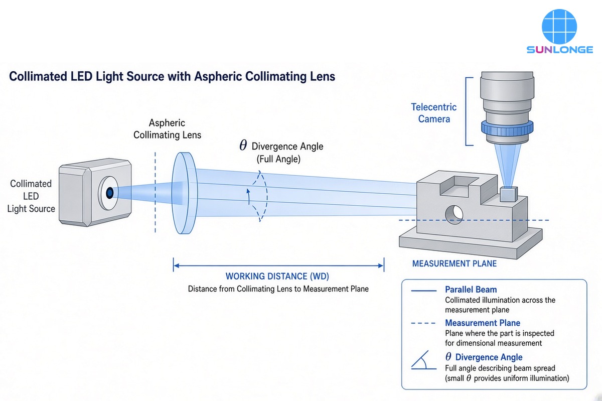
- Working-distance sensitivity. A divergent beam spreads; irradiance falls and the illuminated patch grows as the part moves away. Collimated output keeps a more stable spot size and intensity over a useful working-distance window—important when fixtures cannot place every part at the same height.
- Field uniformity. For video measuring machines and optical comparators, a soft intensity gradient across the field shifts edge thresholds from left to right and creates apparent dimensional bias.
- Alignment with telecentric optics. Highly collimated (or telecentric) illumination must stay aligned with the lens acceptance cone. Edmund Optics notes that even about one degree of misalignment can make a telecentric illuminator appear extremely dim and lose edge contrast. Collimation helps accuracy when the source, part, and lens share an optical axis.
For laboratory and OEM measurement benches that need adjustable aiming without rebuilding the fixture, a collimated LED on a gooseneck—with a defined beam area and dimming—often beats a large diffuse panel that floods the booth with uncontrolled angles.
What “Good Enough” Collimation Looks Like in a Gauge Spec
When you write or review a measurement lighting spec, ask for numbers that map to edge integrity:
- Residual divergence (or emitter size + collimator focal length so you can estimate it).
- Beam / irradiated area at the stated working distance.
- Wavelength (shorter wavelengths can reduce diffraction blur once geometric blur is controlled; Noctvision’s example prefers blue ~460 nm once collimation has cut geometric blur to ~1.5 px).
- Dimming range and stability so exposure and camera gain stay in a linear, low-noise regime.
- Mounting / aiming that keeps the beam coaxial with the metrology axis after fixture changes.
A diffuse panel that only lists lumen output does not answer those questions.
Sunlonge Collimated LED Sources for Measurement Illumination
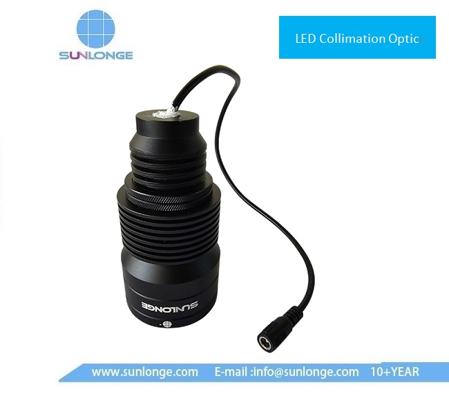
Sunlonge’s collimated LED family is built around a high-NA aspherical collimating lens, modular wavelengths, and practical lab/OEM mounting—not a bare LED behind a diffuser.
SLC9300 — larger beam for instrument and bench illumination
Published highlights from the SLC9300 product page:
| Parameter | SLC9300 (published) |
| Electric power | 30 W class |
| Beam / irradiated area | about 60–150 mm (focus/focal-length adjustment) |
| Dimming | 10–100% (rotary + modulator; product copy also describes 0–100% excitation control) |
| Optics | High-NA aspherical collimating lens; SM2 thread options for microscope / epi ports |
| Mechanics | Flexible gooseneck (~600 mm arm), rotatable head, round base ~138×10 mm; lamp head ~63×116 mm; ~2.3 kg without AC modulator |
| Example peak wavelengths / max optical power (table) | 365 nm / 2000 mW; 405 nm / 1500 mW; 450 nm / 3000 mW; 530 nm / 1300 mW; 630 nm / 1300 mW (FWHM depends on LED) |
That adjustable irradiated area is useful when one instrument must cover both small gauge pins and larger machined contours without swapping the entire backlight.
SLC6300 — compact collimated LED for tighter spots
| Parameter | SLC6300 (published) |
| Electric power | 5 W |
| Optical spot size | about 30–80 mm |
| Dimming | 10–100% |
| Lifetime (published) | >10,000 h |
| Wavelength coverage | broad LED menu from UV through near-IR (product table lists peaks from 365 nm into the 1400–1500 nmregion) |
| Size / weight | roughly 80×40 mm, ~0.1 kg without accessories |
The wide wavelength menu matters for metrology and lab instruments that need a specific contrast band (for example blue for silhouette diffraction, red/NIR for certain coatings, or UV for fluorescence-assisted feature marking)—without abandoning collimated delivery.
Honest Comparison: Collimated LED Source vs Typical Alternatives
No vendor should invent a laboratory accuracy percentage without a shared fixture. What can be compared honestly is how lighting choices affect the error budget:
| Factor | Typical diffuse / uncollimated LED panel | Commodity “spot LED” without defined collimation | Sunlonge collimated LED source (SLC9300 / SLC6300) |
| Angular control | Wide Lambertian-like fill of the lens NA | Often unspecified; hotspot + spill | Aspheric collimation aimed at parallel delivery |
| Edge blur on thick parts | Scales with thickness × tan(θ); can exceed defect size | Unpredictable | Designed to keep residual divergence small vs diffuse panels |
| Beam area control | Soft fall-off; hard to stop light wrapping | Fixed hotspot | Published adjustable areas (≈60–150 mm / 30–80 mm) |
| Intensity control for cameras | Coarse or none | Often on/off or limited | Continuous dimming (published 10–100%) |
| Integration | Large panels hard to aim into a microscope or compact gauge | Tripod clamps | Gooseneck + threads / OEM mounts |
| Wavelength choice | Often white only | Few SKUs | Multiple narrowband LED options on published tables |
Illustrative engineering estimate (not a Sunlonge lab certificate): if a 3 mm part’s diffuse-edge band is ~75 µm and a well-collimated setup reduces it toward ~15 µm, nearly 60 µm of geometric edge uncertainty is removed before software runs. On a ±10 µm tolerance feature, that difference decides whether the gauge is trustworthy or merely repeatable-around-the-wrong-value. Always confirm with your own edge-profile and GR&R tests.
Practical Integration Tips for Metrology and Dimensional Inspection
- Plot the edge profile first. Before arguing about sub-pixel parameters, capture a line profile across the silhouette. If the band is many pixels wide and lopsided, fix illumination geometry before tuning software.
- Match divergence to lens NA. Residual source divergence should stay well below the imaging acceptance angle when silhouette integrity is the goal.
- Keep coaxial alignment. Especially with telecentric lenses, small tilt can kill brightness and contrast.
- Use dimming instead of camera gain. Raise irradiance into a clean exposure window; avoid noisy high-gain captures that look “bright” but measure poorly.
- Standardize working distance. Record WD, beam area setting, and dimmer position in the measurement procedure so operators do not recreate a new photometric setup each shift.
- Choose wavelength for the residual blur budget. Once geometric blur is controlled, diffraction and material reflectance still matter—blue is often preferred for fine silhouettes; other bands may be better for material contrast.
Where Sunlonge Fits in the Instrument Bill of Materials
For OEMs building compact optical measurement heads, or labs upgrading a video measuring microscope illuminator, a collimated LED source is a modular subsystem: stable LED, aspheric collimation, dimming electronics, and a mechanical interface that can aim at microplates, gauge pins, or custom fixtures. Sunlonge’s SLC9300 and SLC6300 are positioned for exactly that class of work—microscope illumination, general-purpose collimated excitation/illumination, and direct illumination of inspection targets—rather than as anonymous panel lights.
Review the collimated LED product family and detailed datasheets here: Sunlonge Collimated LED Light Sources (https://www.sunlonge.com/products/collimated-led-light-sources).
Key Takeaways
- Optical measurement accuracy depends on edge geometry and field irradiance, not only camera megapixels.
- Residual beam divergence turns thick-part silhouettes into blur bands roughly following thickness × tan(θ); collimation shrinks that band.
- Public application examples show diffuse vs collimated blur dropping from on the order of ~7.6 px to ~1.5 px on a 3 mm part under stated optics—enough to change whether a 30–40 µm feature is separable from lighting error.
- A collimated LED source with defined beam area, aspheric collimation, and fine dimming gives metrology teams controllable, documentable lighting—Sunlonge’s SLC9300 and SLC6300 publish those parameters for instrument builders and lab users.
If your dimensional inspection results move when thickness, lot finish, or fixture height changes, inspect the illumination angles before rewriting the vision recipe.